- Rackable Systems 4U chassis
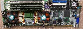
- Dual 1 GHz Pentium-3 processors
- 1 GB RAM
- 12 slot PCI Backplane
- Redundant chassis 400 watt ATX hot-swap ATX power supplies
- 250GB, 7200 rpm Hard-drive
- 52X CDROM-drive
- 4 - 4", 49 cfm chassis fans.
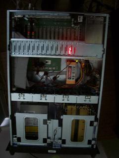
431B Technoland 4U steel chassis with six 5.25" and one 3.5"
open drive bays, and one hidden 3.5" drive bay. It will accommodate most 14-slot backplanes.
The front door is lockable and provides access to the drive bays.
The status indicators and dust filters are also located behind the front door.
This particular chassis model provides a Fault Detection Module (FDM) to monitor internal temperature, CPU fans and system fans. The FDM provides fault status indication at the front panel and an audible alarm when a fault is detected.
NOTE: At this time, the FDM is ONLY monitoring internal temperature and system fans. It is not monitoring the CPU fans or the DOM power supply fans.
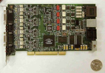
- 1 GHz, dual Celeron (Plll) processor
- Single board computer with 512MB of RAM.
- Dual LAN controllers: 10 BaseT/100 Base TX and 1000 Base T Ethernet
- There four DIMM sockets to accommodate 2GB SDRAM. Presently, it is configured with 512 MB.
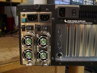 These are 400 watt hot swappable power supplies. If one should fail there is an audible alarm (separate from the FDM above) as well as front panel indication. Some earlier chassis do not have the front panel indication.
~
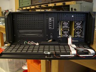 Behind the drop down front door are the drive bays and numerous recessed
push buttons and a rocker switch. The rocker switch is used for reseting the
FDM audio alarm. The larger push button near the bottom is for turning on the
ATX power supplies. Just above the power on button are five recessed push
buttons. These are for different resets in the system. The top button labeled,
POWER BUZZER RESET is presently not hooked up. Just below the power
buzzer reset is a recessed push button labeled, RESET 1. This button is
the hard reset for the CPU. The other recessed push buttons, RESET 2, RESET
3 and RESET 4 have no function at this time.
Behind the drop down front door are the drive bays and numerous recessed
push buttons and a rocker switch. The rocker switch is used for reseting the
FDM audio alarm. The larger push button near the bottom is for turning on the
ATX power supplies. Just above the power on button are five recessed push
buttons. These are for different resets in the system. The top button labeled,
POWER BUZZER RESET is presently not hooked up. Just below the power
buzzer reset is a recessed push button labeled, RESET 1. This button is
the hard reset for the CPU. The other recessed push buttons, RESET 2, RESET
3 and RESET 4 have no function at this time.
 Two Acopian model
 W48NT370 48V, 175 watt switching regulated power supplies in series
to provide 96 VDC , one 0 to +48V, one 0 to -48V to power up to 60 DOM's.
(http://www.acopian.com/single-s-narrow-m.html)
These power supplies have dual internal fans.