An additional 'serial' cable will be required between the clock unit and each of the Wisconsin PCs. These ordinary ethernet cables can be taken from the terminal server interface equipment removed along with the earlier DESY CPCI DAQ for string 18 installed in January 2000. This equipment was put aside in November when opening up space in the string 18 rack earlier in the season for the string-18 upgrade.
NOTE!!
Any internal oscillators on the DOMCOM PC Boards MUST be
disabled.
To disable oscillator U4, jumper JP1 should be removed, and jumper JP2
moved to short pin 2 and pin 3 together. Jumper JP3 should be
moved
to short pin 5 to pin 6. If U1 and/or U2 are present, they should
be removed, or should have the VCC pin desoldered from the PC
board.
Any other oscillator on the board can beat with the reference
oscillator
provided by the clock unit , possibly degrading the timing measurement
accuracy of the DOMCOM Test Boards.
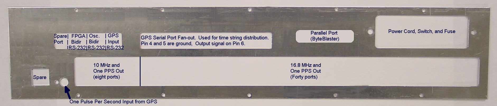
Figure 1.
Reference Oscillator Subsystem rear panel. Key to the location
of inputs and outputs. The LED adjacent to the one PPS input
blinks
during power-up only. This is normal.
2. Connect the forty red (ethernet) cables from each DOMCOM Test Board to a 16.8 MHz port on the clock unit. Note that each DOMCOM Test Board has two RJ-45 connectors, one with plastic housing (lower) and one with integrated metal shield (upper). Use the upper, shielded connector. Use only the 16.8 MHz outputs of the clock unit, not the 10 MHz outputs (the eight nearest the one PPS input connector). All red cables should be of the same length. (Please report any length discrepancies. They will be taken account of in the analysis.)
3. Connect the One Pulse Per Second output of a GPS clock to the gold LEMO connector in the rear corner of the clock unit. Note the left side of Figure 1 above.
4. Connect a standard ethernet cable (four pairs RJ-45 to RJ-45) from the RS-232 port labeled "GPS" to the RJ-45 to DB-9 adapter labeled "DOMCOM to GPS." Plug the DB-9 connector into the serial port of a GPS clock which has been programmed to deliver the ascii time string every second. Any available GPS clock in MAPO may be used to provide this signal. It doesn't have to be the same clock used in step 2 above.
5. Connect one of the included special serial cables from a port of the terminal server to the RS-232 port labeled OSC. Two cables were shipped with the clock unit in a plastic bag. (These cables are serial port NULL MODEM cables for connection to the terminal server.) Make note of the terminal server port number used.
6. Connect the other included special serial cable from a port of the terminal server to the RS-232 port labeled PGA. Make note of the terminal server port number.
7. Connect a standard ethernet cable from one of the eight GPS time string serial output ports (upper middle of rear panel) to an input of the terminal server. Make note of the terminal server port number.
8. Connect 5 standard ethernet cables from five of the seven remaining GPS time string serial output ports to RJ-45 to DB-9 adapters labeled "DOMCOM PC". Plug those adapters into the upper serial port connector on the back of each of the Wisconsin CPUs.
9. Connect the parallel port cable from the back of the clock unit to the parallel port connector on the back of the nearest of the DOMCOM PCs. Make note of which DOMCOM PC the parallel port cable is plugged into.
10. Connect a power cord from the clock unit to a socket on the UPS output power distribution network.
11. Turn on the power switch adjacent to the power cord socket on the back of the clock unit. You should hear or see the fan start up. After a short time, the red LED on the front panel of the clock unit should start blinking at a 1/2 Hz rate.
12. Mail to John Jacobsen, Azriel Goldschmidt, and Gerald Przybylski the port numbers (three of them) of the terminal server noted in step 5, 6 and 7, and name of the PC used for the parallel port download cable.
Once all the hardware is interconnected and powered up, data taking should be possible immediately.
As soon as we in Berkeley hear that everything is in place, we will attempt to confirm functionality over the network.
If there are any questions about this installation, contact  ,
or by phone...
,
or by phone...
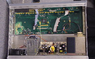
Figure 2.
Top view of clock unit. From left to right across the bottom of photo:
fan, covered 5V power supply, open frame 24V power supply, and rubidium
oscillator, gray, far right, with black heat sink. Main PCB in upper
part
of photo.
Remarks:
The PGA RS-232 port is set for 38.4 kilo baud, eight bit, no parity, one stop bit.
The OSC RS-232 port is set for 9600 baud, eight bit, no parity, two stop bits.
The time fan-out ports for the GPS clock time string deliver exactly the same RS-232 output settings as the GPS clock.
The clock outputs are on pin 1 and pin 2 of the RJ-45 connector.
The one pulse per second outputs are on pin 3 and pin 6 of the RJ-45
connector.
The RS-232 TX and RX lines are pin 3 and pin 6 of the RJ-45 serial port connectors. Pin 4 and pin 5 are return lines.
The Rubidium oscillator will take a few minutes to lock after power-up. During that times its heater will be consuming a great deal of power (see manual). After lock-up, the unit will draw significantly less power.
The Rubidium oscillator will slew (smoothly) the correct frequency and phase for ten to twenty hours before delivering its advertised performance. This is normal. The errors introduced into the data by this phase matching process may be undetectable in the physics data, or will at most require a small correction.
In the light of the long time to lock, power cycling of the clock unit should be avoided.
Questions and comments on this page should be directed to ,
Lawrence Berkeley National
Laboratory.