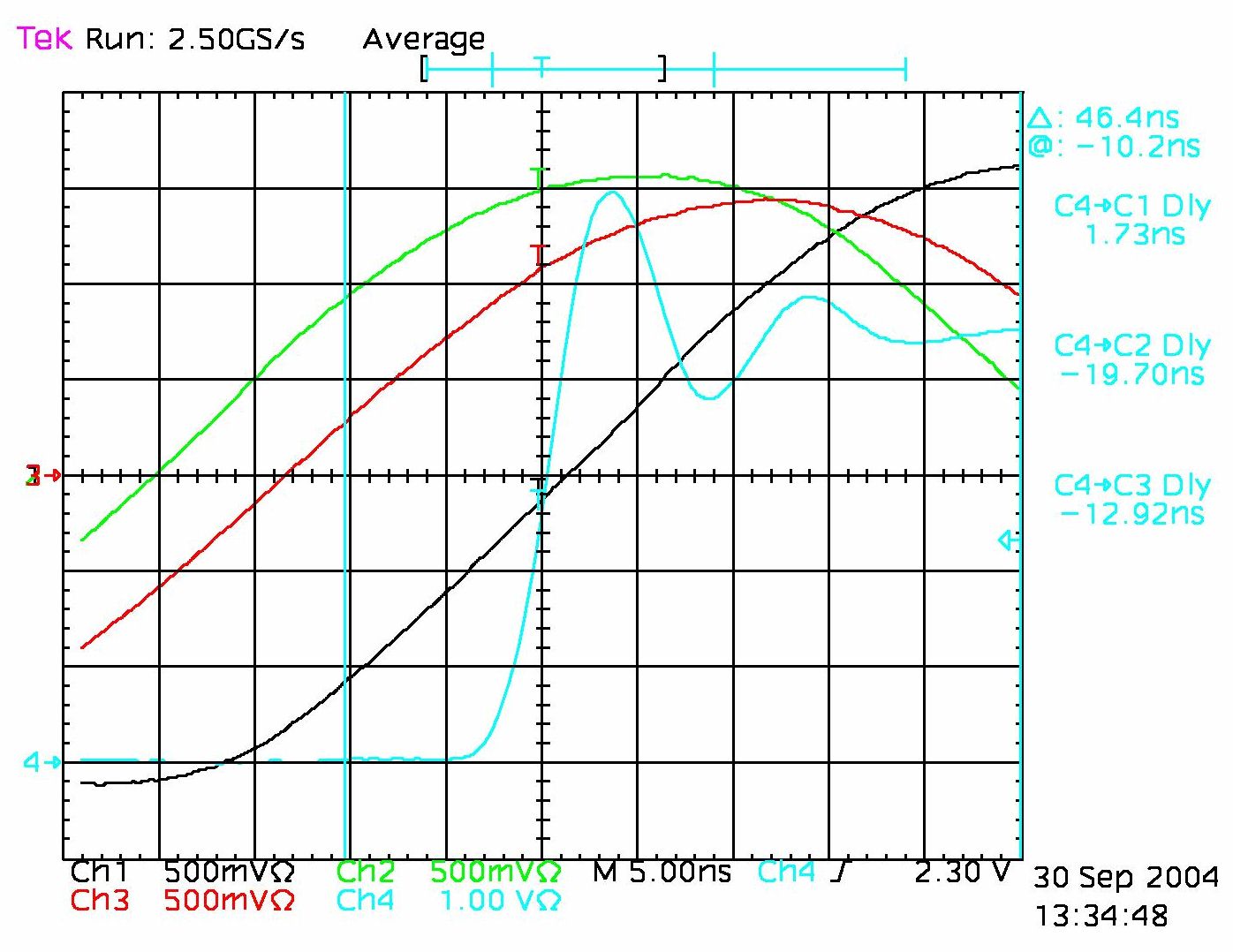
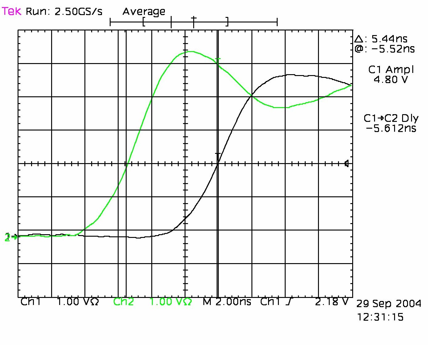
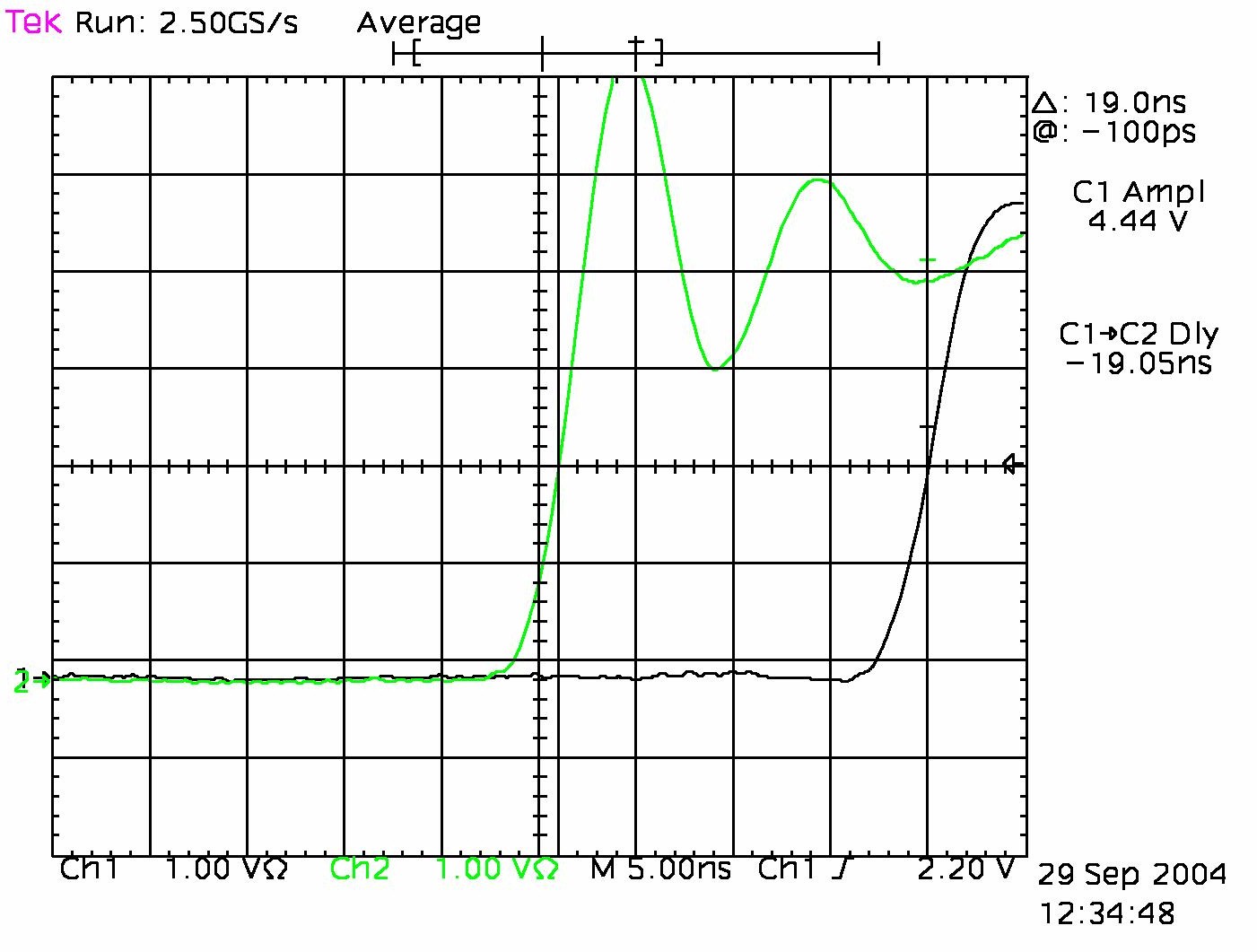
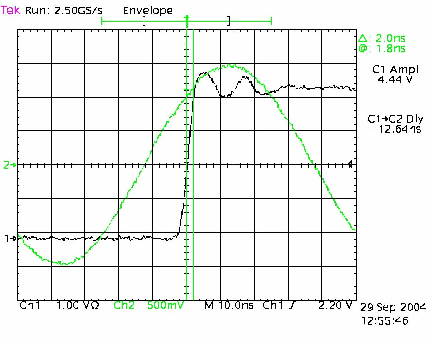
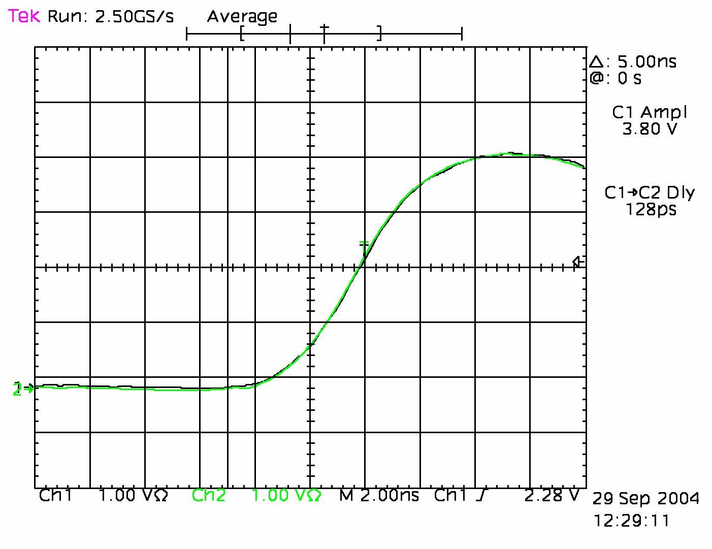
10
MHz Phase Skew for three outputs of an ET6000 GPS clock
|
J3e, J3f and J7 10 MHz Sin
outputs; (trigger
J4) Average 16 seconds
|
J3e, J3f and J7 10 MHz Sin
outputs; (trigger
J4) 20 seconds, ∞ persistance
|
|
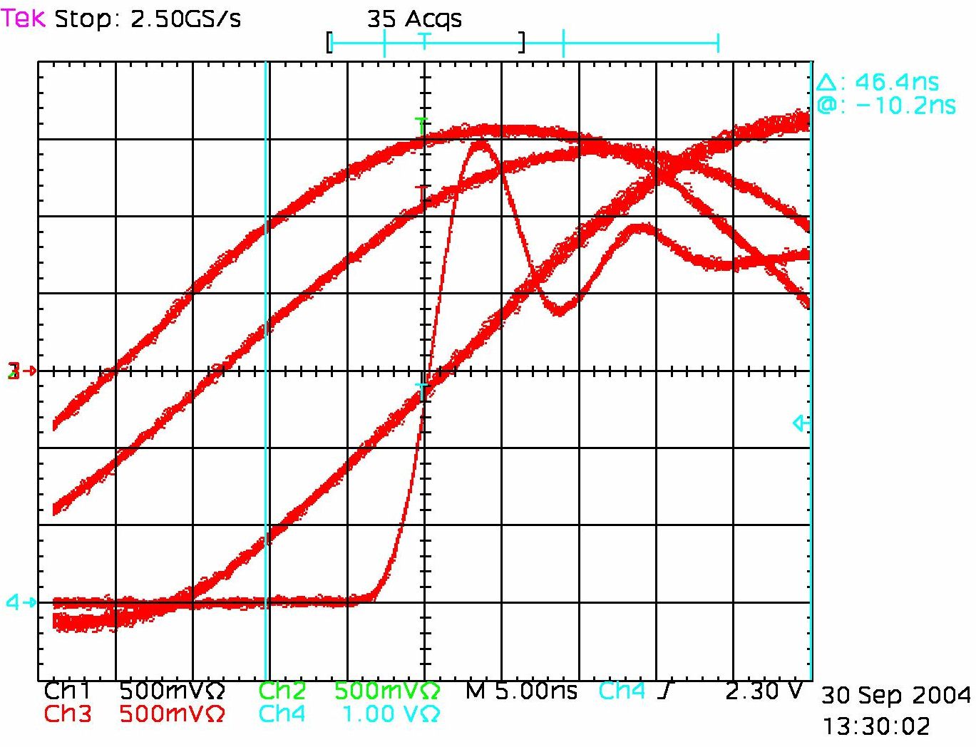
The channel assignment is the same as in the image to the left.
I read this as about 1ns jitter with respect to the channel 4
triggering reference.
|
|
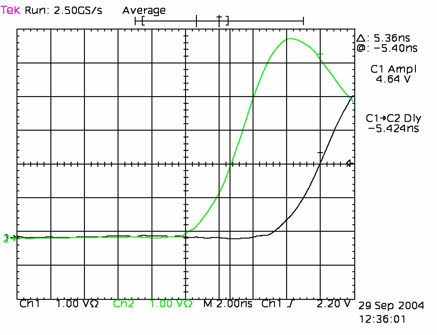
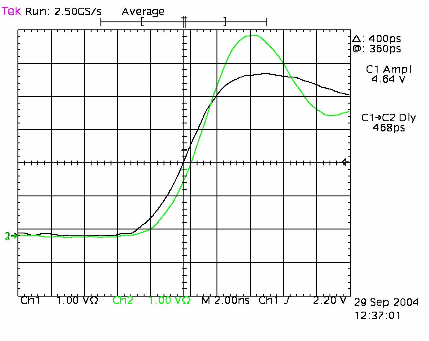
Oscilloscope
Channel Input Skew Verificaton
Ch1, Ch2, Ch3: matched 10 ns Cables // Ch4:
~5ns
|
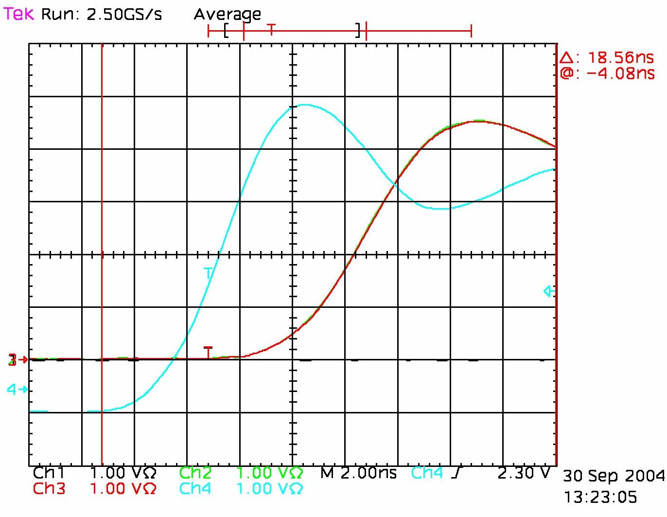
Ch1 to Ch3 match
|
Ch2 to Ch3 match
|
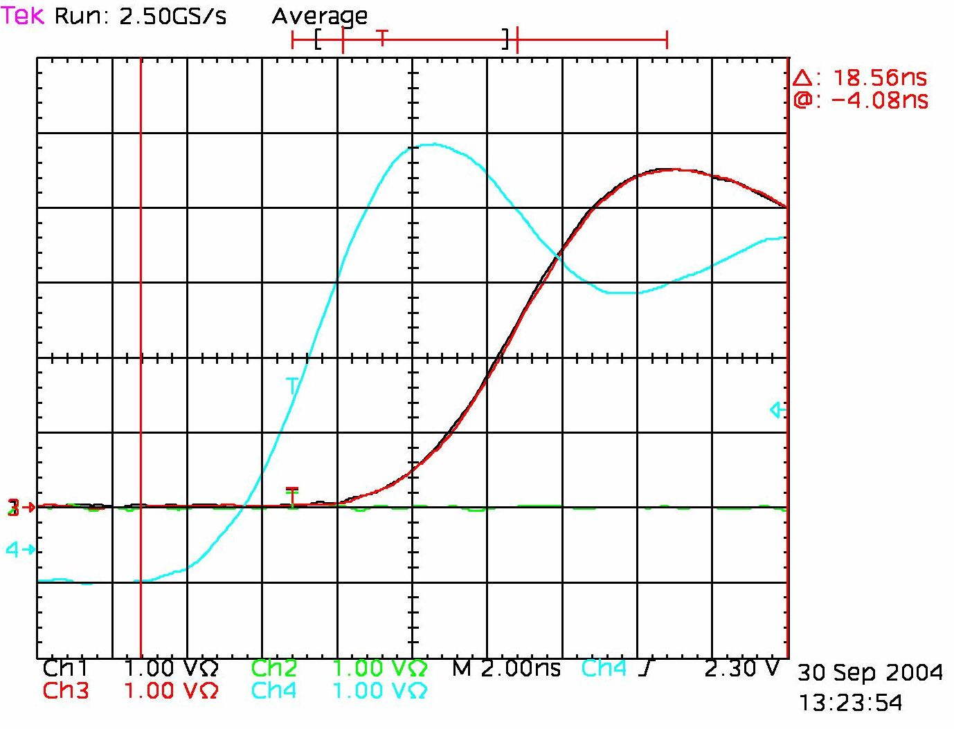
Ch4 is a common trigger signal selected for convenience
|
Ch4 is a common trigger signal selected for convenience
|
From the
above screen-snaps, it is obvious that the the cable and input,
together, for both Ch 1 and Ch2 are very closely matched. This
condition is needed for the comparisons that follow:
|
| One
Pulse Per Second Channel to Channel Skew |
 J8 to
J9 delay J8 to
J9 delay
|
Condition: Jitter
during several seconds of acquisition ???
|
 J6 to J9
delay J6 to J9
delay
|
|
 J5 to J9
delay J5 to J9
delay
|
|
 J4 to J9
delay J4 to J9
delay
|
|
 J7
to J9 delay J7
to J9 delay
|
|
|
|
|
|
|
|
|
Channel skew for relative timing
measurements of pulse output skew
|
|
|