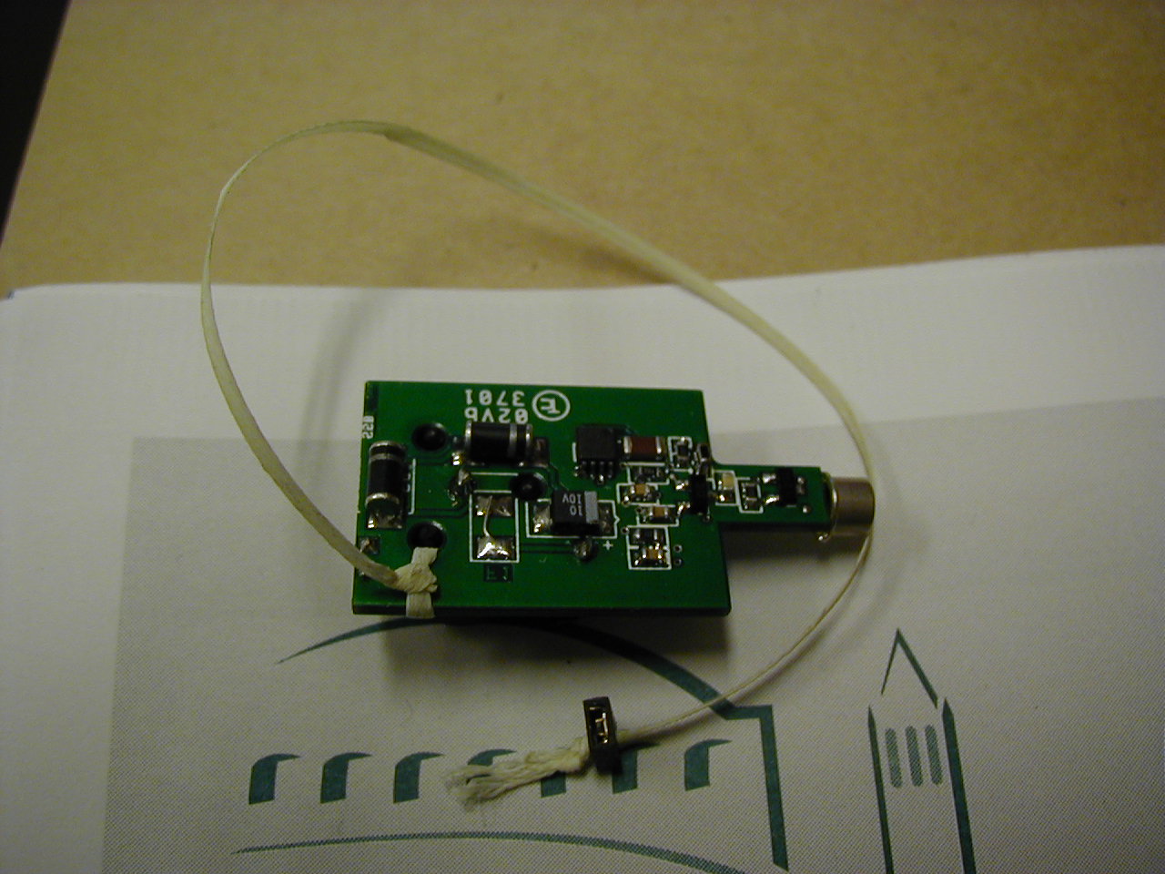
The basic pulser consists of a UV light emitting diode (manufactured
by Nichia of Japan), an energy storage capacitor and a periodic
discharging
circuit. .The large value resistor charges a capacitor, which is
discharged
through a low on-resistance fast switch in series with the LED.
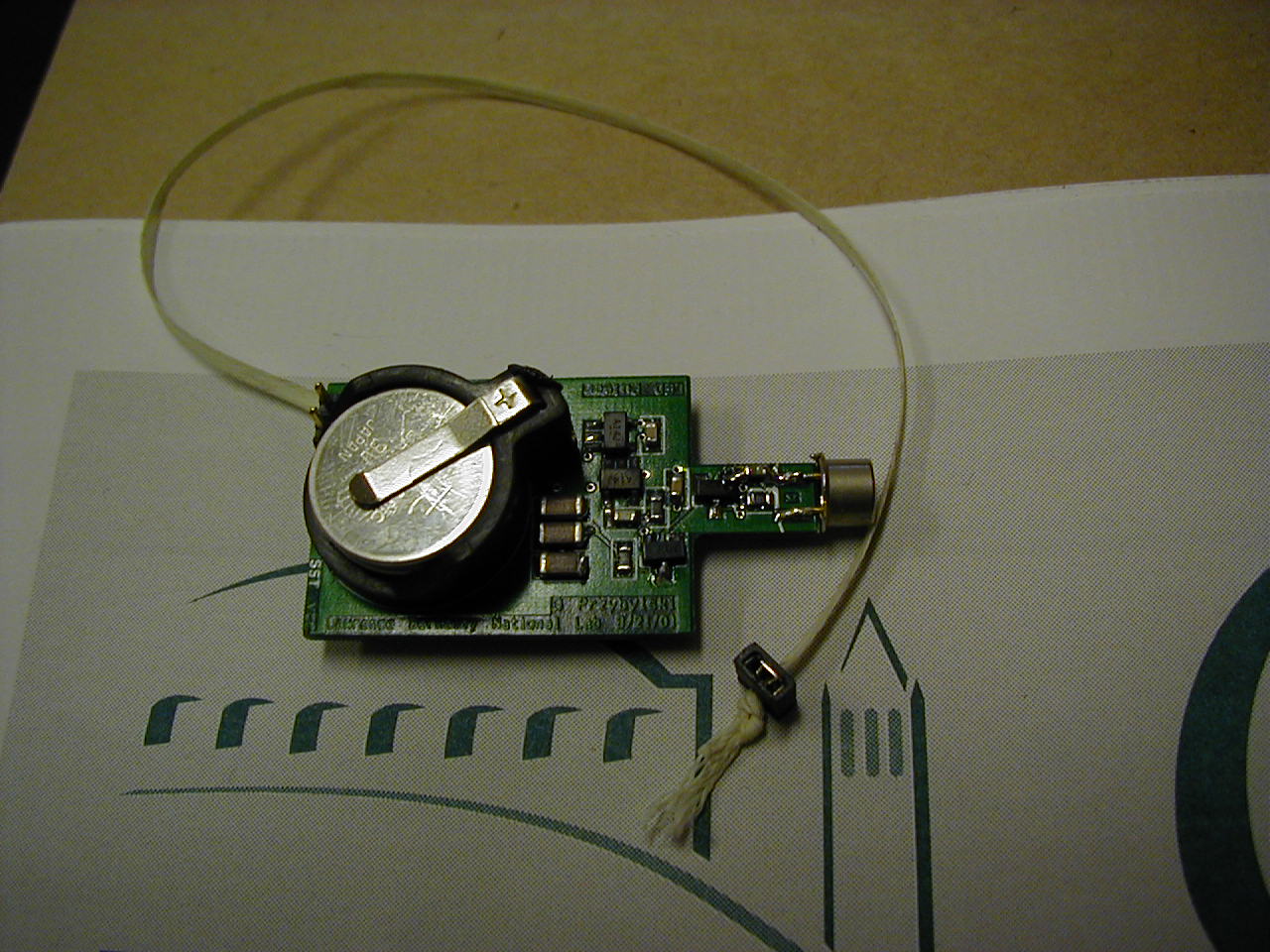
Surface mount components make possible a rather small footprint for
the complete package.
Low power consumption of the circuit makes possible the operation for hours from 12 mm coin cell batteries.
The proof of the pudding...
A 0.5 ohm resistor in series with the energy storage capacitor ground end permits one to make a discharge current pulse measurement. The discharge waveform, below,
It shows a rather short waveform without much evidence of ringing
after
return to baseline. The green trace is the falling cathode voltage as
the
switch turns on.. The energy storage capacitor is comparable in
size
to the zero bias capacitance of the LED. The measurement was made
before the circuit was optimized.
After optimization of the circuit by adjusting some component values,
screen snaps of the light output waveform were taken.
Four separate screen snaps were taken with a Tektronix TDS644
oscilloscope
with 500 MHz bandwidth and 2 GSPS sampling rate, so the results are
pretty
believable. Notable is that the light pulse shape is roughly the
same for each of these typical pulses. Click on the image for an
EPS version.
 |
 |
 |
 |
For reference, the fast photomultiplier delivered a remarkably short pulse from a spontaneous single photoelectron event. The signal from the fast PMT displayed above is the convolution of the LED light pulse waveform with the impulse response of the photomultiplier tube (as depicted in the SPE response below)
.
John Wolf mounted the components on the printed circuit board.
Fred Bieser made measurements of his own...
The PCB layout was done with OrCAD layout, and fabricated by TelTec
PCB.
Questions and comments about the pulser can be directed to Gerald
Przybylski,