 |
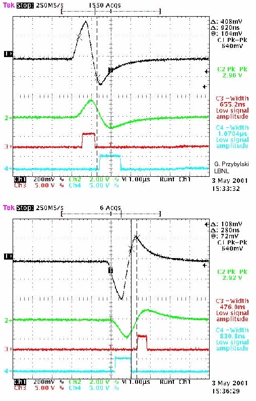
The channel 1 and 2 signals to the left are received by the testboard
form the DOM through about 2 km of twisted quad cable. Trace 1 is
the signal input to the ADC. Trace 2 is the signal input to analog comparators,
the output of which is connected to the FPGA. The lower traces show
the outputs of digital discriminators in the FPGA, each output feeding
an output pin monitored by a scope probe. The center of the digital
discriminator is set to 512 ADC counts, with a window extending 64 counts
above (red trace) and 64 counts below center (blue trace).
Notice that the lower trace is consistently wider than the upper trace.
The asymmetry occurs because the 512 ADC count center value does not match
the average driver baseline level input to the ADC. |